An optocoupler or optoisolator, is a device that contains a light-emitting diode (LED) and a photosensor ( photodetector, such as a photoresistor, a photodiode, a phototransistor, …etc ). The purpose of an optocoupler is to transfer signals from one circuit to another yet keep them galvanically isolated.
Here I want to show you how to check if an optocoupler is working. So I’ve chosen one of the most commonly used optocouplers ( PC123 – 4 pins) for the demonstration, but you can use the same principle for all optocouplers ( note: check the datasheet first ).
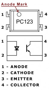
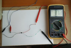
Using the diagram in the right identify the pins; first the anode and cathode of the LED ( in this case pins 1 and 2 ), and then using an ohmmeter set on the ‘X1 Ohm’ domain, measure between pins 1 and 2, and you should get one reading measuring one way and no reading the opposite way (just like you check a diode). If you get a value either way or no value at all, then certainly there is a problem with the LED, and you should find another optocoupler.
Step 2
If the LED is good then we should check the phototransistor, you could measure it with the ohmmeter just like the LED between pins 3 and 4 ( the emitter and collector ), and you should get a high resistance value both ways if the phototransistor is good. If you’ll get no reading at all, is probably because most phototransistors have such high resistance between emitter and collector that the ohmmeter can’t measure; if this is the case you could connect two ohmmeters in series thus increasing the measuring domain; …although i think most don’t have two meters so i recommend the ’empirical’ method, presuming you have a variable DC regulated power supply.
Connect the ohmmeter ( X1K Ohm or X10K Ohm ) between emitter and collector ( 3 and 4 ) like this: red probe to collector and black probe to emitter. Now connect a resistor of a few hundred ohms ( ~300 ohms ) in series with the LED anode, after this turn on the power supply and start increasing the voltage from 0 to 2…3 volts, and you should be able to see on the ohmmeter how the output resistance decreases as the input voltage increases and viceversa.
Notes: Optocoupler PC123 datasheet


